Radxa X4 N100 Cluster Build Log - Part 5: Assembly Guide
Requirements:
- 3D Printer / printed parts
- Soldering Iron
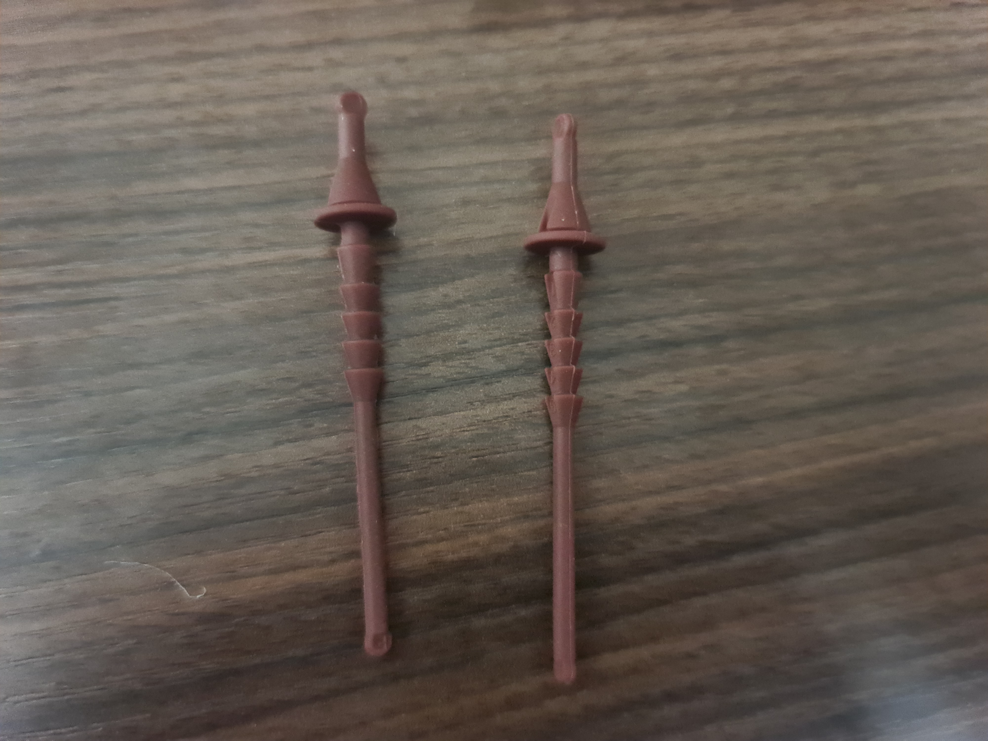
- 4x M3x5x5 brass inserts
- 4x M2.5x5x3.5 brass inserts
- 4x M2.5*6 countersunk screws
- the Radxa X4 N100
- Noctua NF-A4X20 PWM or your 5V PWM fan of choice
- Silicone thermal pads (1mm thickness, as large as possible) / thermal paste
- Time
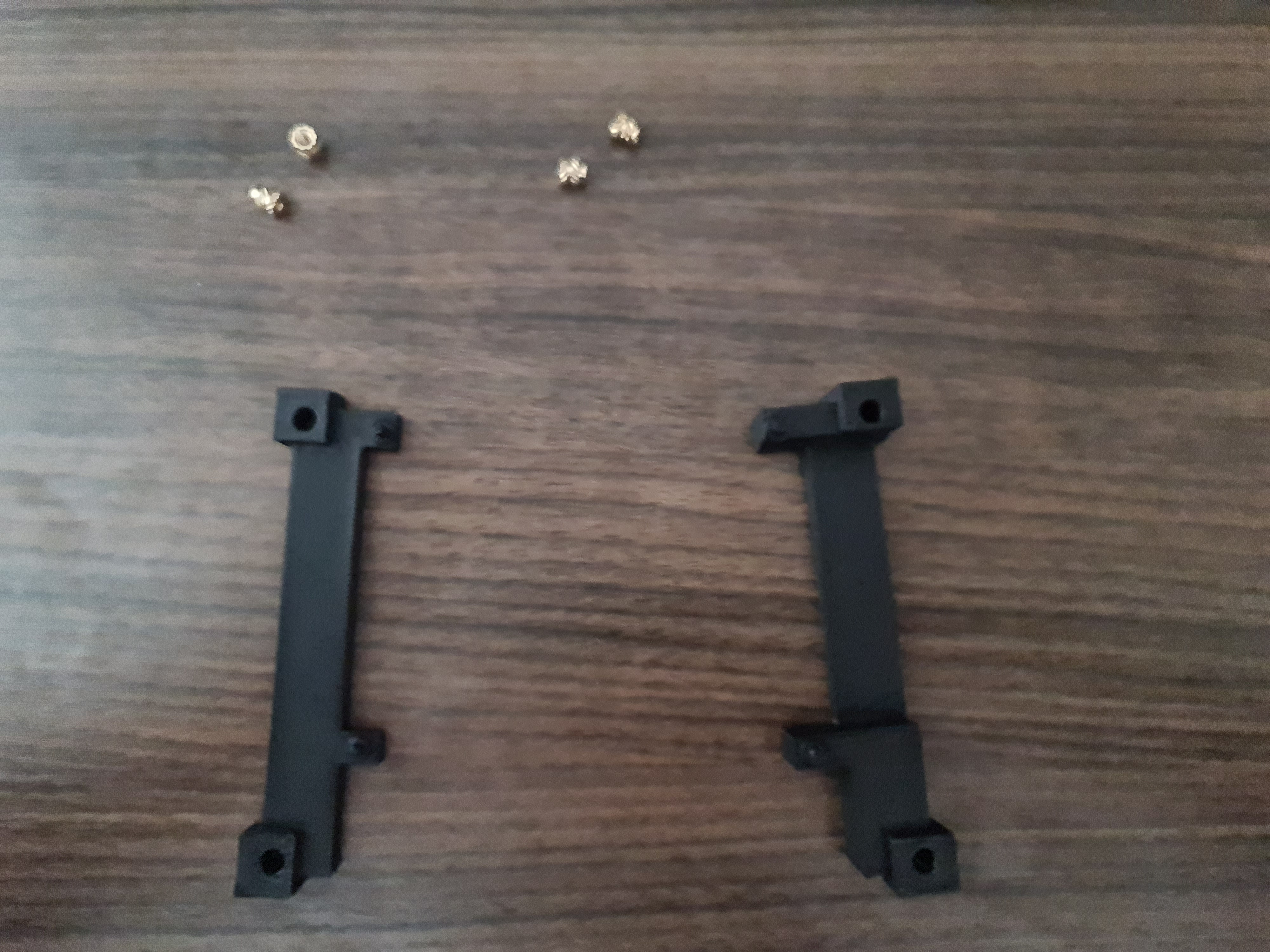
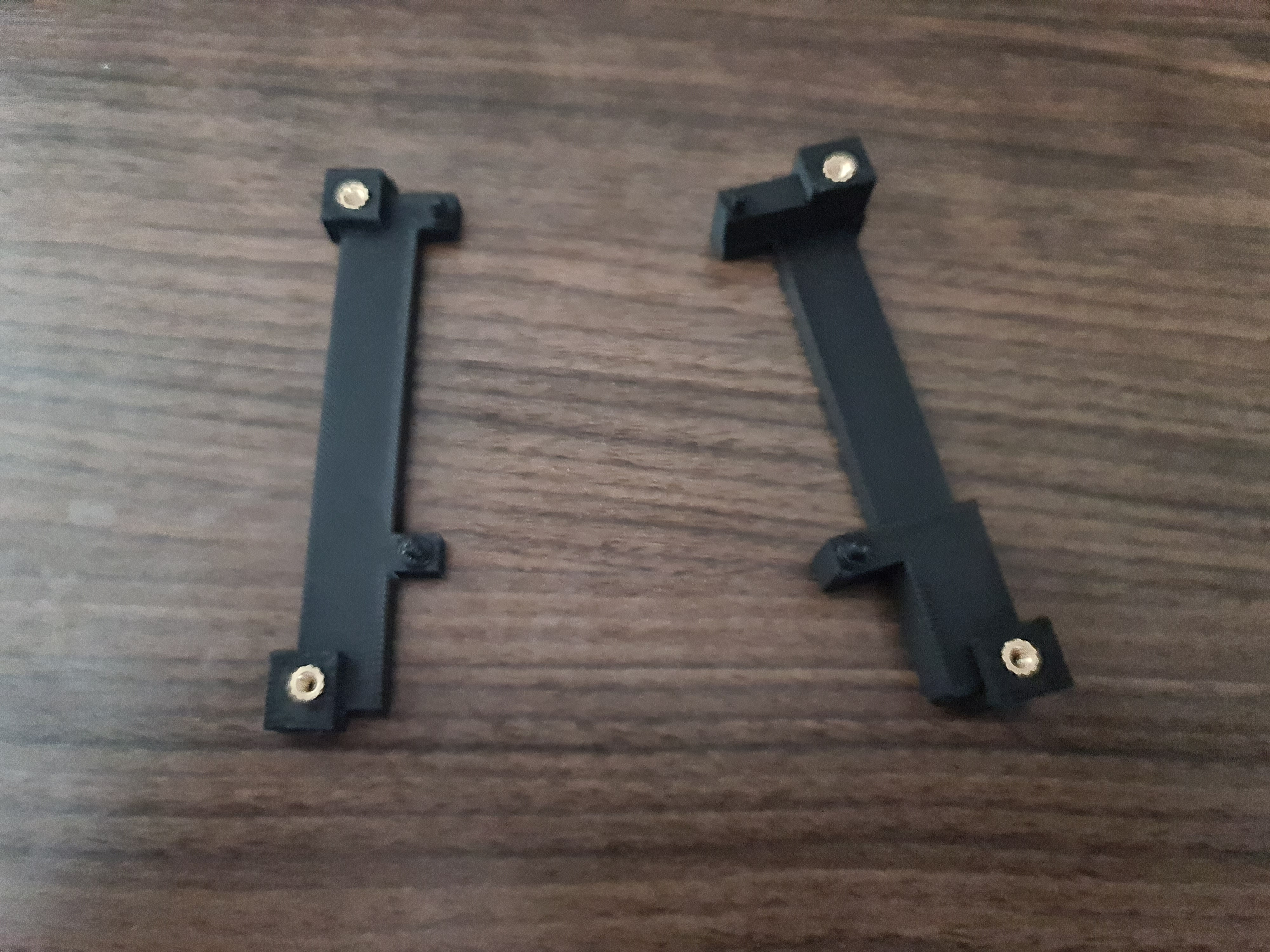
The Brackets
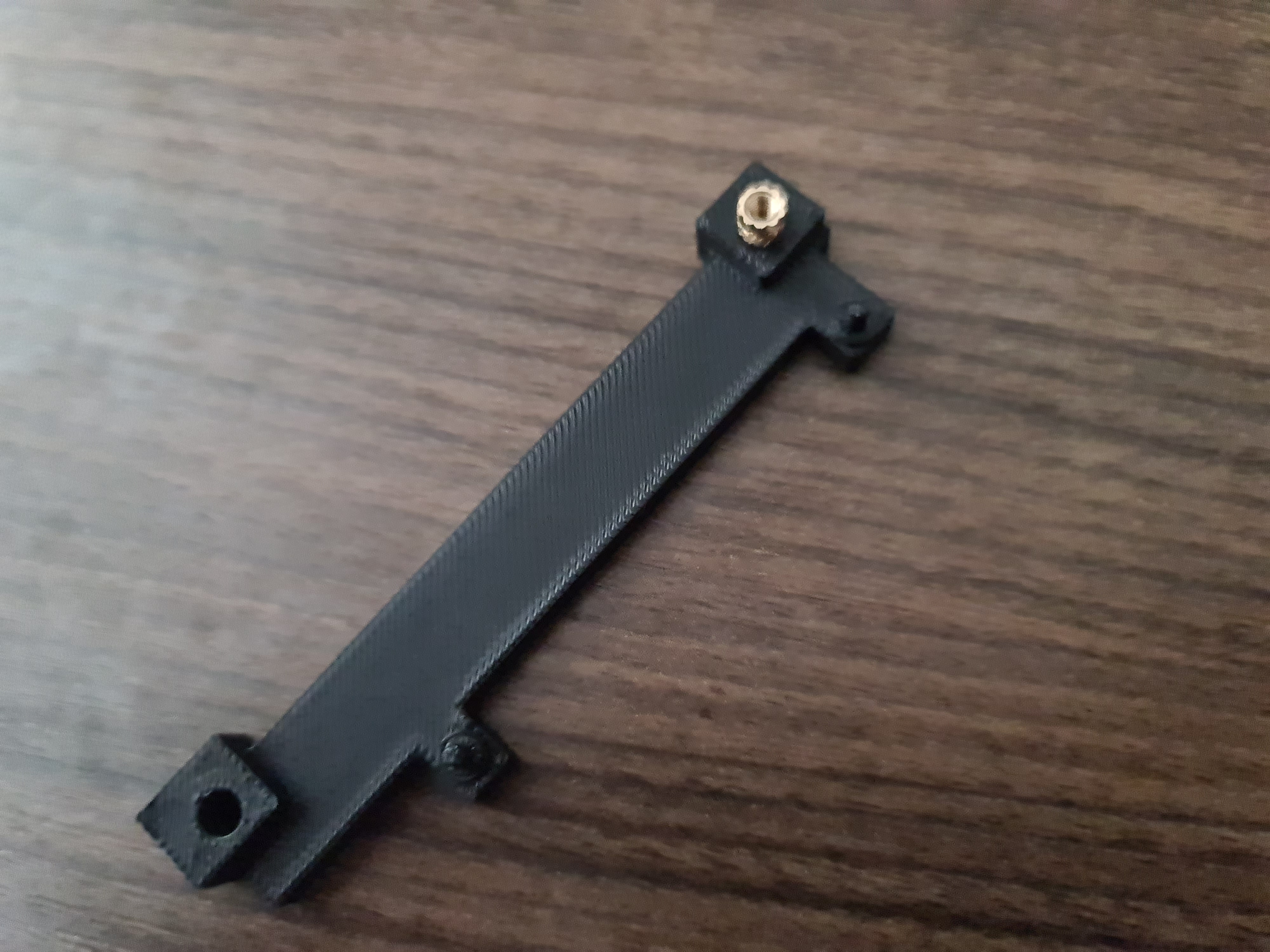
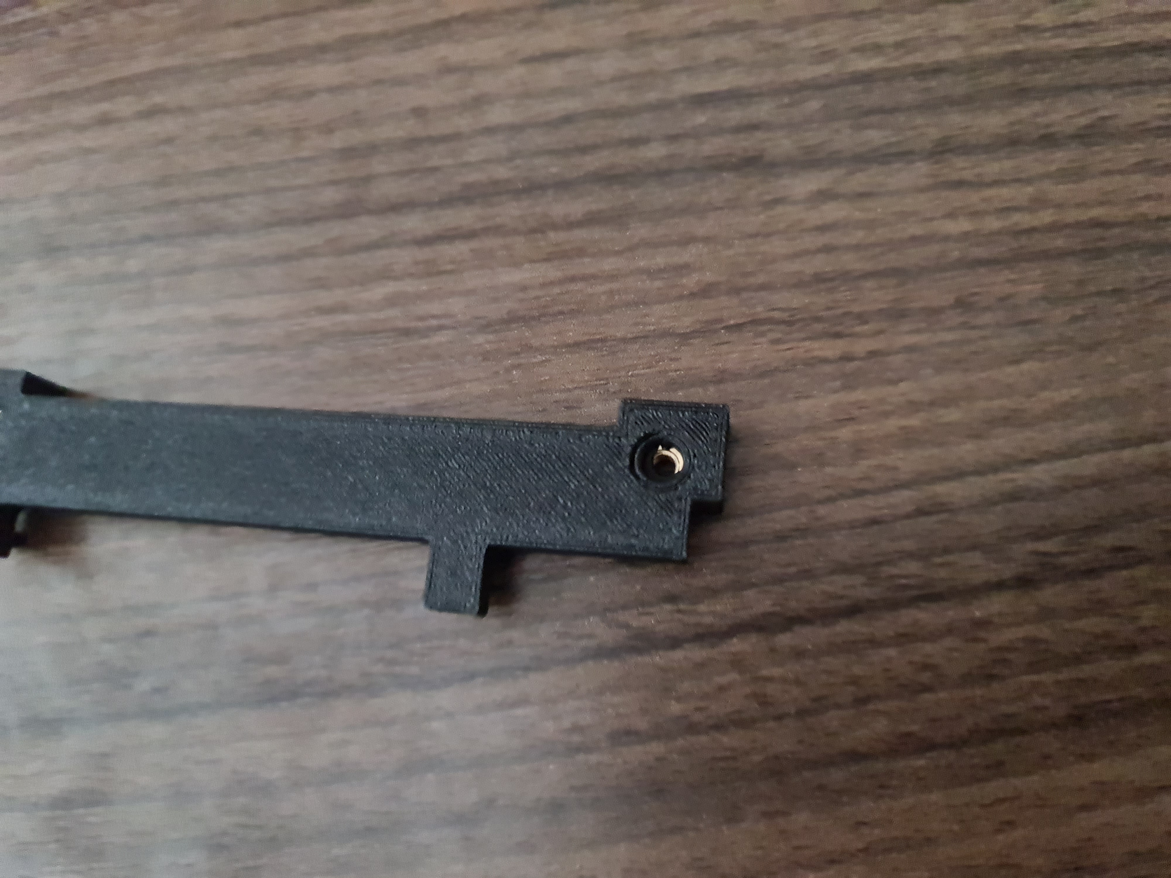
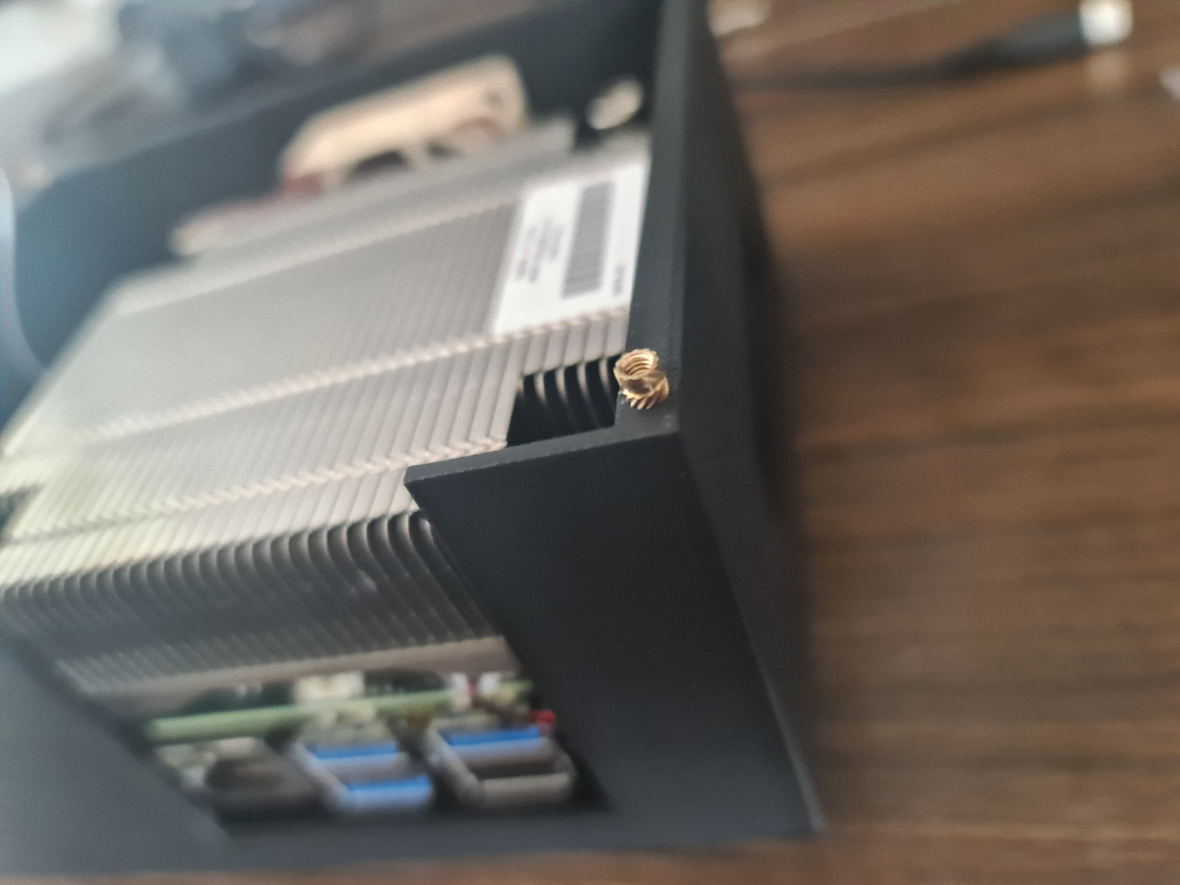
Take the one M3x5x5 brass insert and insert it by hand into one of the holes of a bracket. Make sure the bracket pins look up.
Now take your soldering iron and heat it up. Once it’s hot, take the soldering iron and press it into the brass insert. This will melt the plastic around the insert and make the insert move slowly into the plastic. Make sure to not press too hard, otherwise the insert will go too deep into the plastic, and you won’t be able to screw in a screw later.

Stop before the insert is flush with the plastic. While the insert is still hot, turn the bracket around and press it against a flat surface. This will make the insert flush with the plastic.
Make sure you insert the brass insert straight!
Repeat the process for the other holes.
Mounting the Heatsink and preparing the board
Now to prepare the board turn it on its back to expose the CPU. Make sure the die is clean and if not clean it with some isopropyl alcohol.

Now to make sure there is good thermal transfer between the heatsink and the CPU we need to either apply thermal paste or silicone thermal pads. I decided to use silicone thermal pads, since I was worried about the thermal paste not being thick enough and the heatsink not being flat enough.
I also only had some very small thermal pads, so I had to puzzle them together to cover the CPU. This is not ideal, but it works. Warning thermal pad gore:

Now we need to place the board on the heatsink. Make sure you align the board with the copper base of the heatsink. It needs to be aligned to the right. Do NOT use any force in the next steps, since there are board components which you might risk to break.
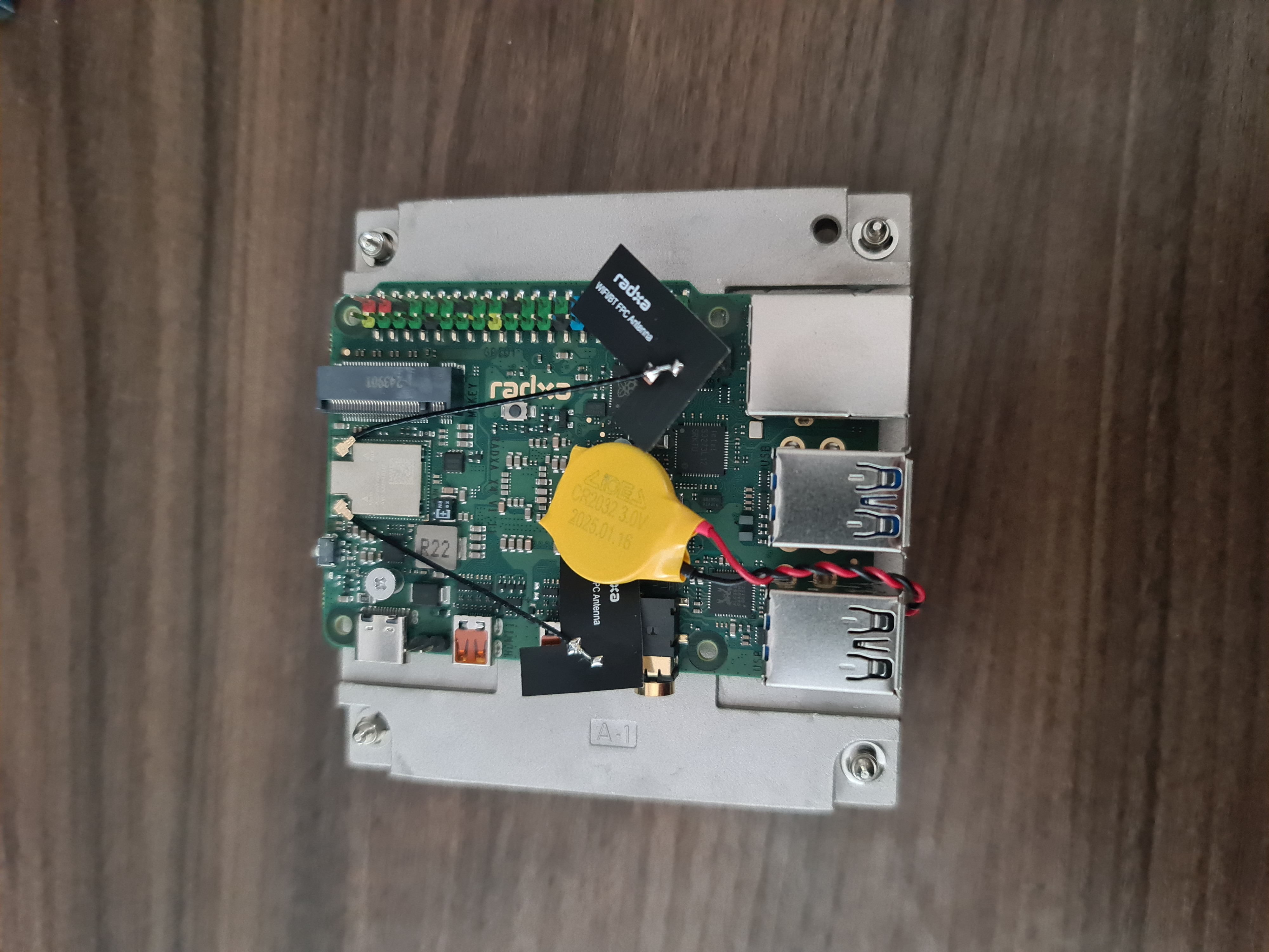
Next we just insert the bracket pins in the mounting holes and lie the brackets on the board without any force. Make sure the inserts are aligned to the heatsink screws.
When everything sits alright begin screwing the screws into the brass inserts. Make sure you don’t screw them in too hard, since this might break the PCB. You should also screw diagonally, so the pressure is even on the CPU and the heatsink.
Try to peek between the board and the heatsink and shine light through the gaps to make sure the board contacts the heatsink.
When you are done, the board should look like this:

Optional:
I removed the WiFi antennas, since I don’t need them and they are at risk of ripping off the board when I insert the board into the case. Do not yank on the antenna, but take a small plastic piece and put it under the connection to remove them.
Attaching the Fan
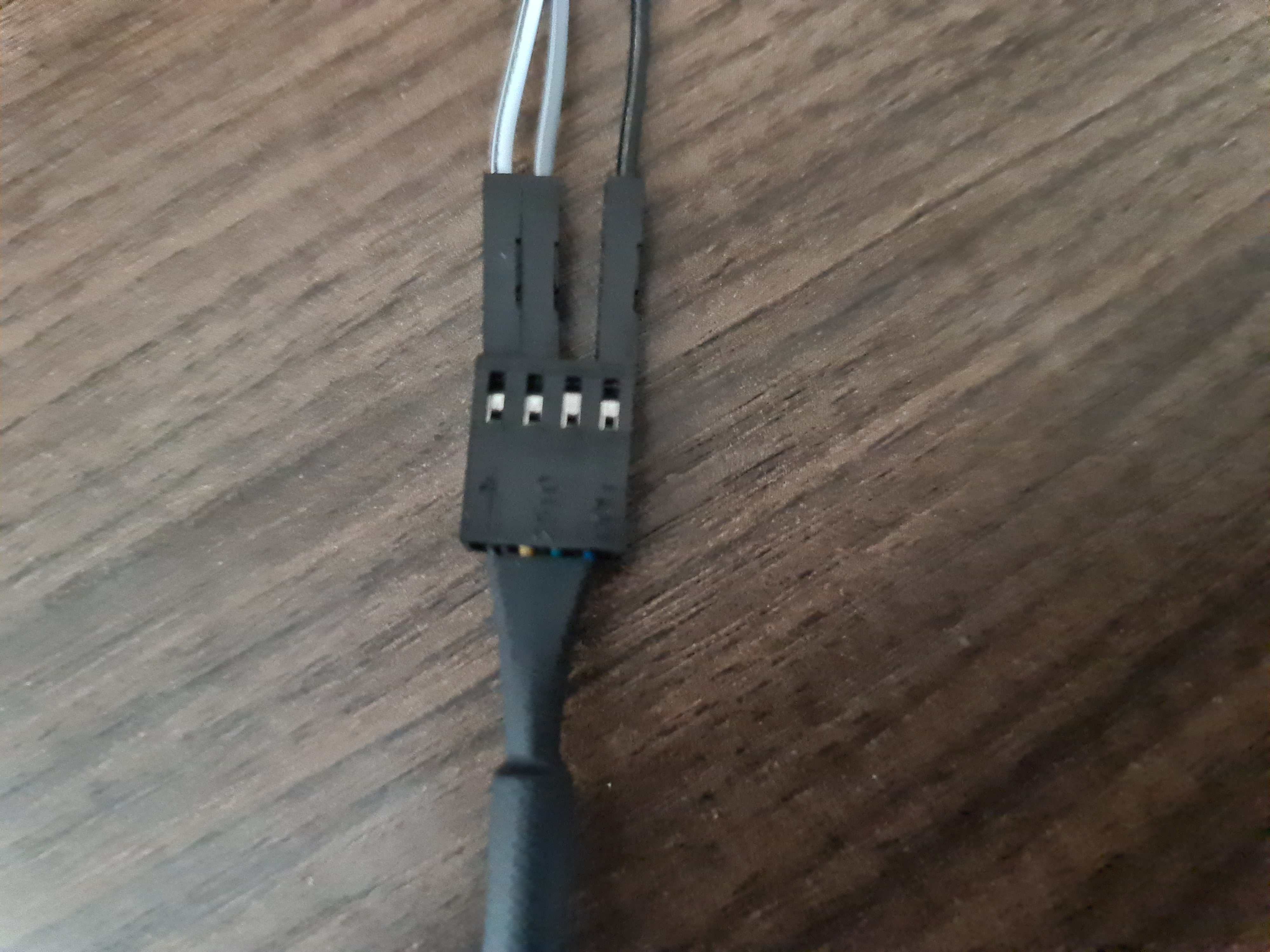
Prepare your jumper cables, you need three male to female ones.

Attach them as shown on the following picture, making note of the colors. The fan is a 5V PWM fan, so the grey wire goes to the 5V pin, the white wire goes to the GND pin and the black wire goes to the PWM pin.
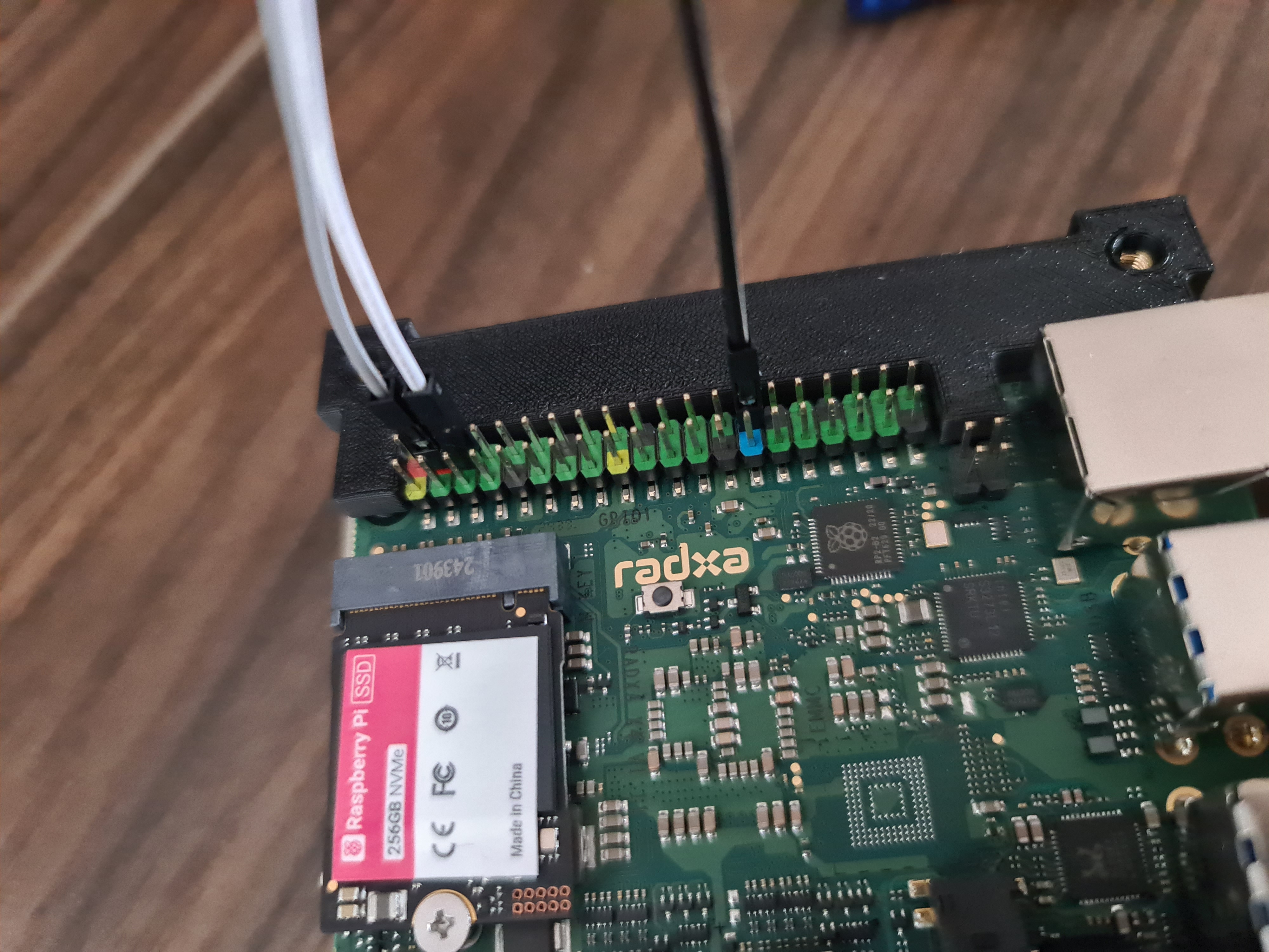
Now attach the male end of the jumper cables to the fan. If you use a different fan, make sure you check the pinout of the fan.
If you attach the cables wrong, you might destroy the fan!
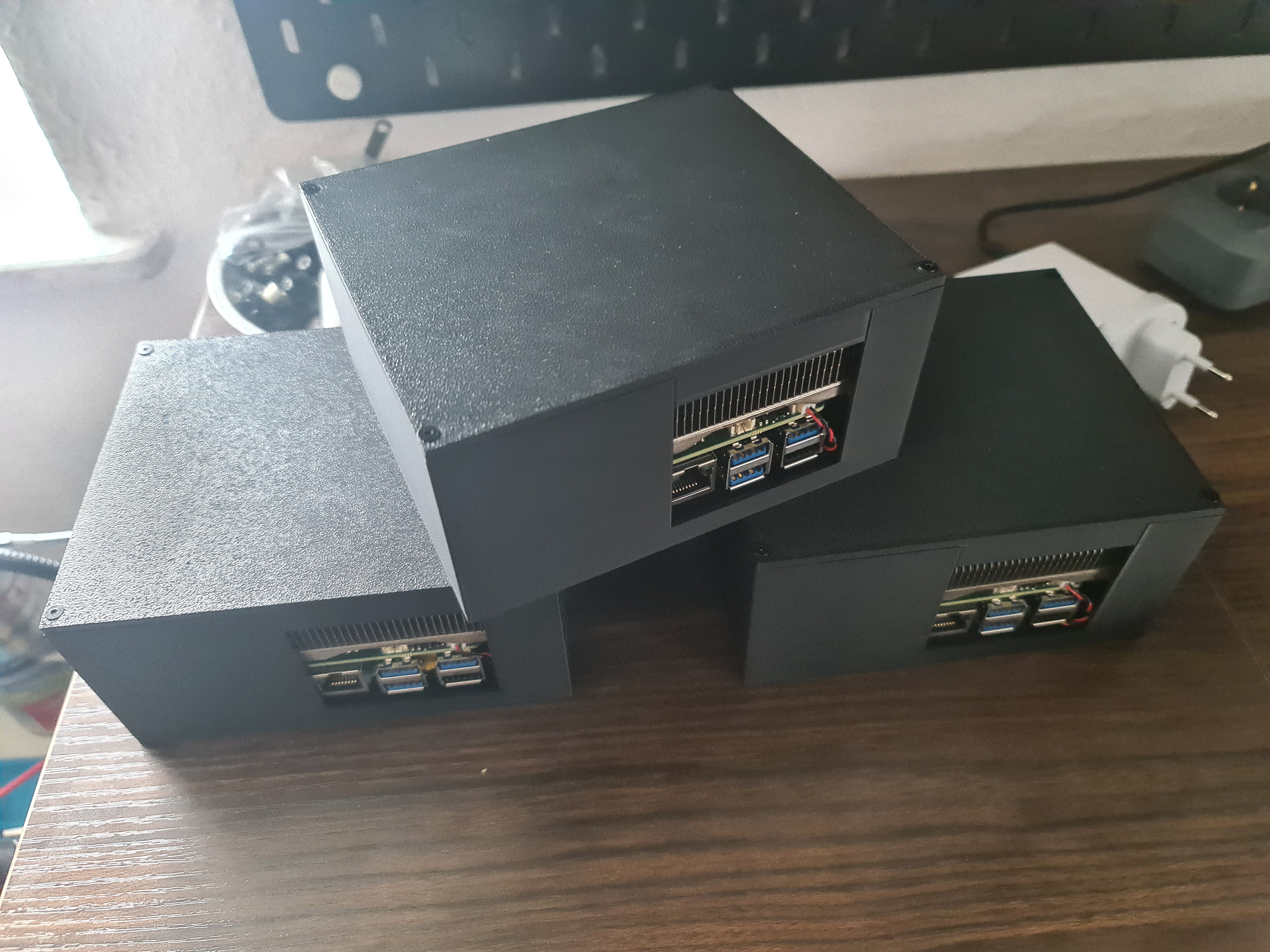
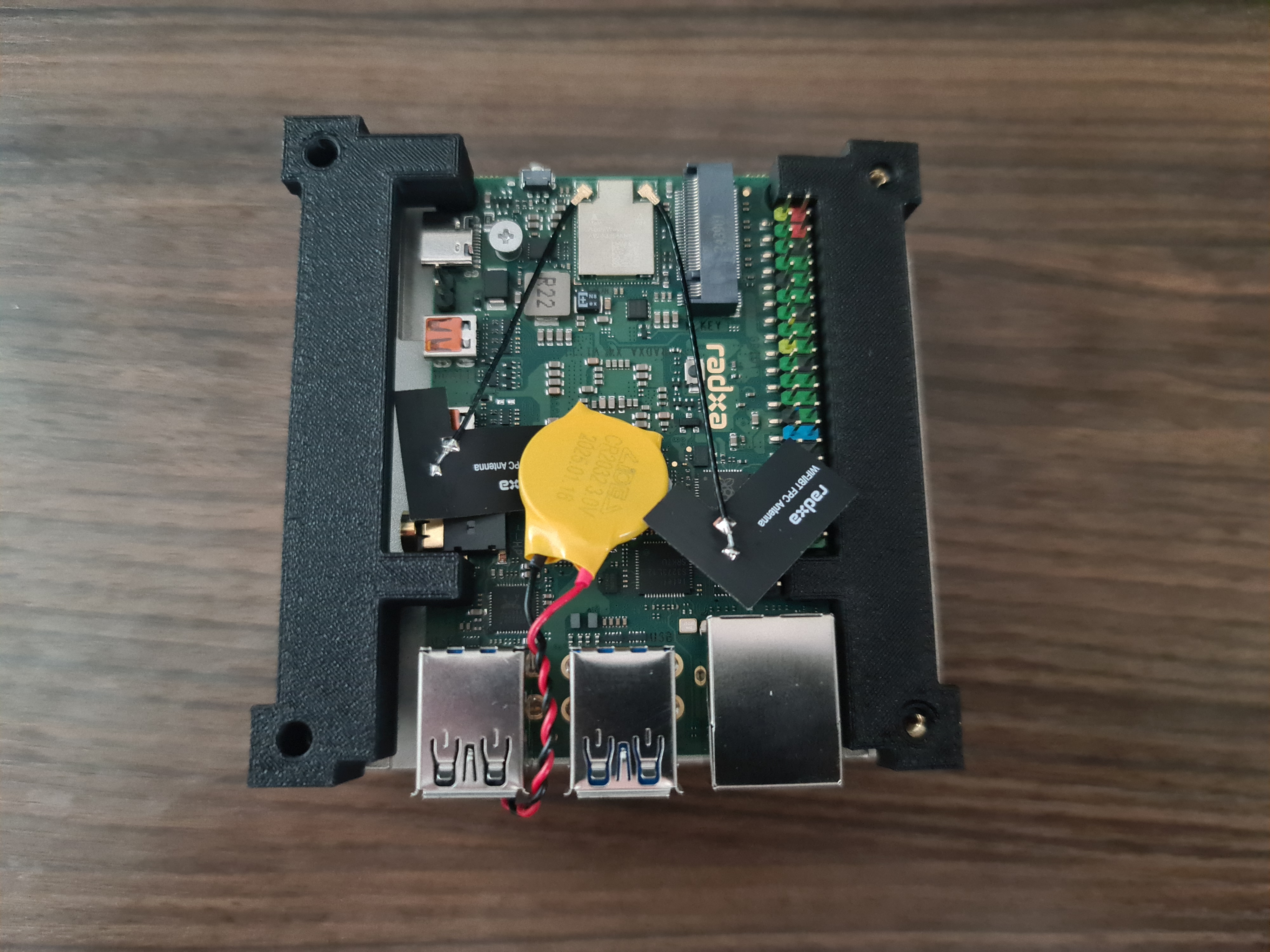
The Case
Similar to the brackets, we need to insert the M2.5x5x3.5 brass inserts into the case. Make sure they are flush and centered. Don’t put the board into the case yet, like in the picture below. The board will be mounted later.
Putting it all together
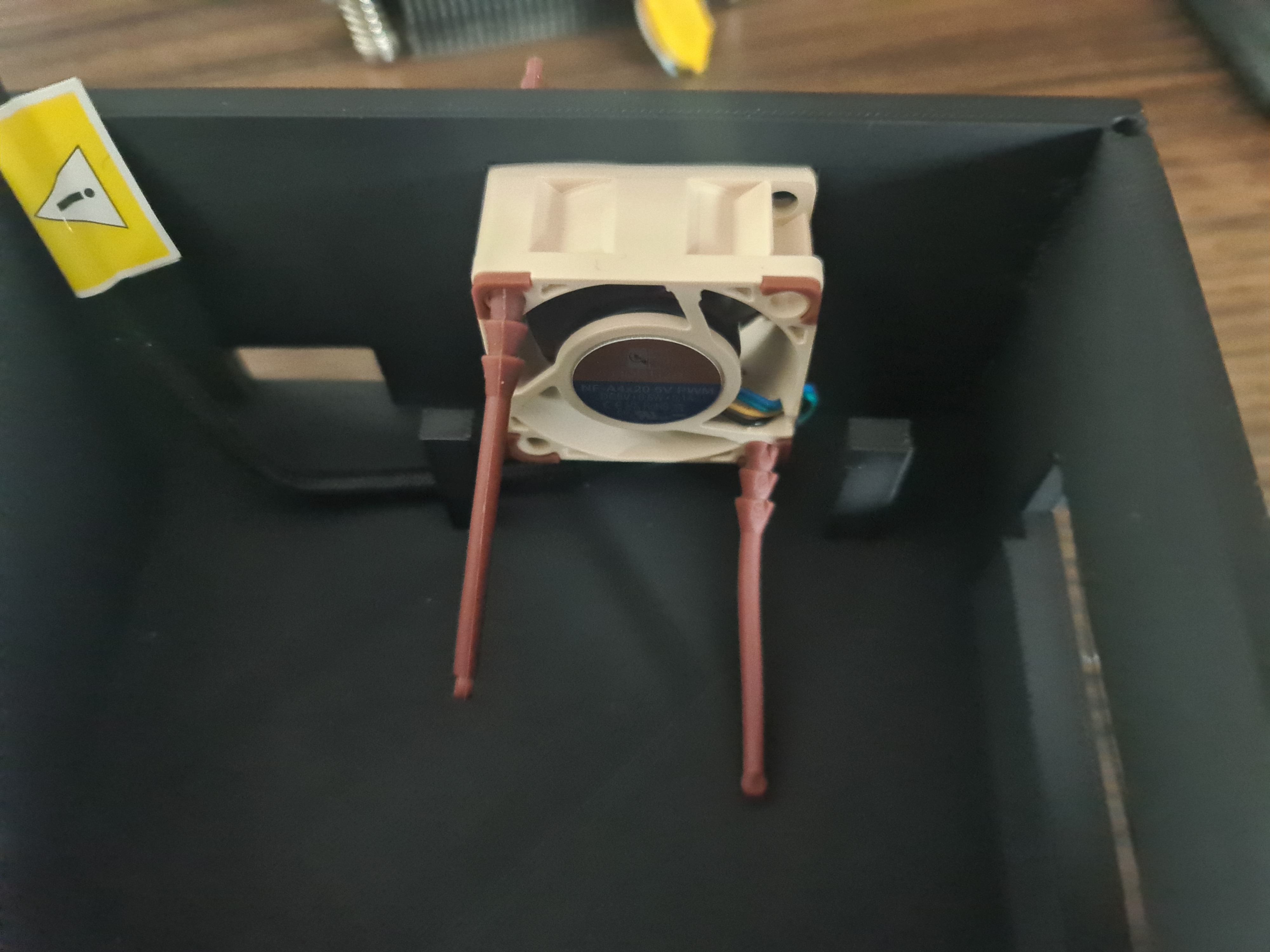
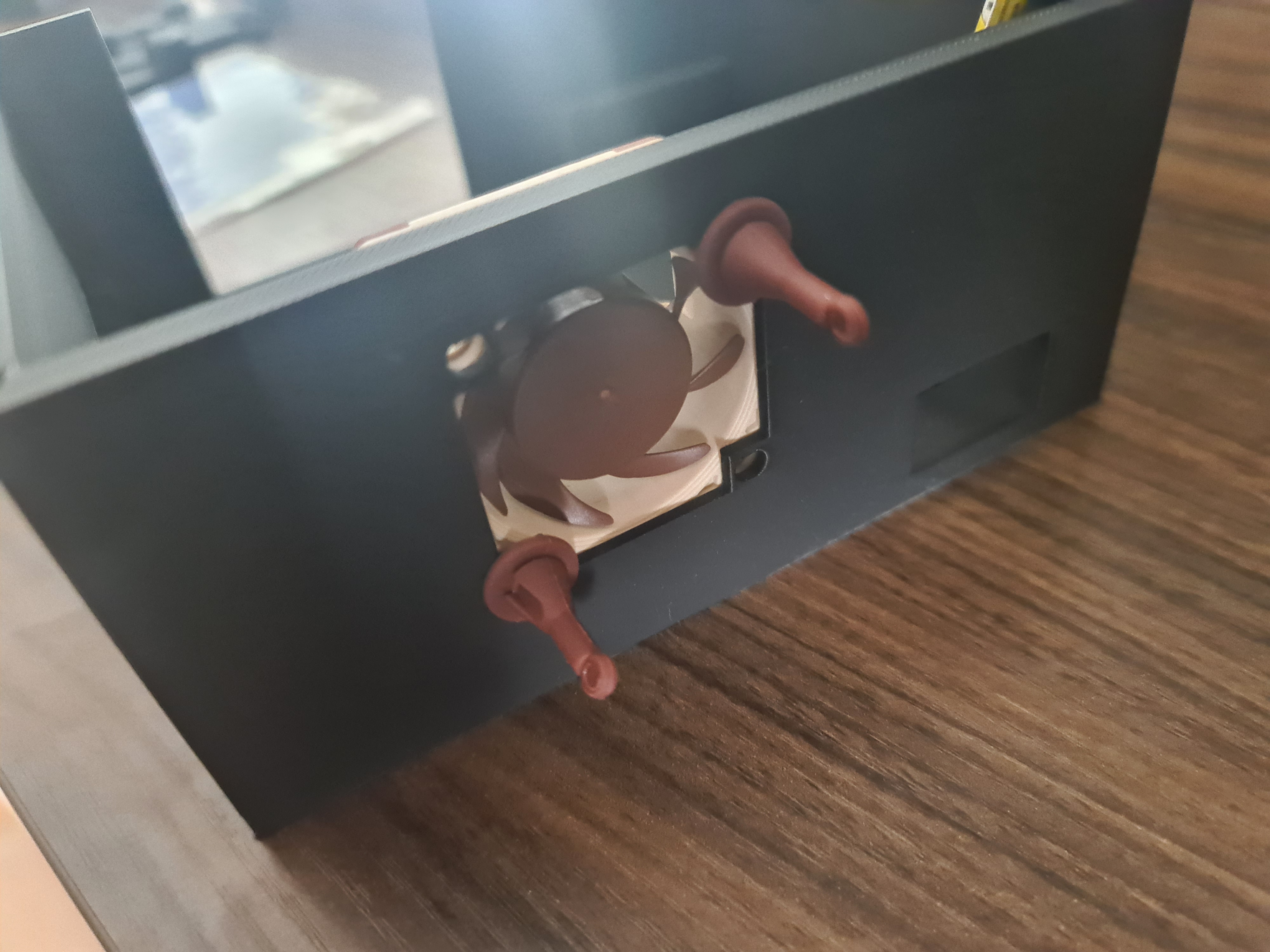
As a first step we insert the fan by hand into the cutout of the case. Make sure that you move the cable under the fan to the left side, so it doesn’t interfere with the other assembly.
Also make sure you insert it in the correct way. The air should push through the heatsink and out of the case. So, from the back to the front.

Using the rubber mounts, we can now mount the fan to the case. The rubber mounts are a little long, so you should cut them down, once they are mounted. I assembled and disassembled the case a few times, so I didn’t cut them down yet.
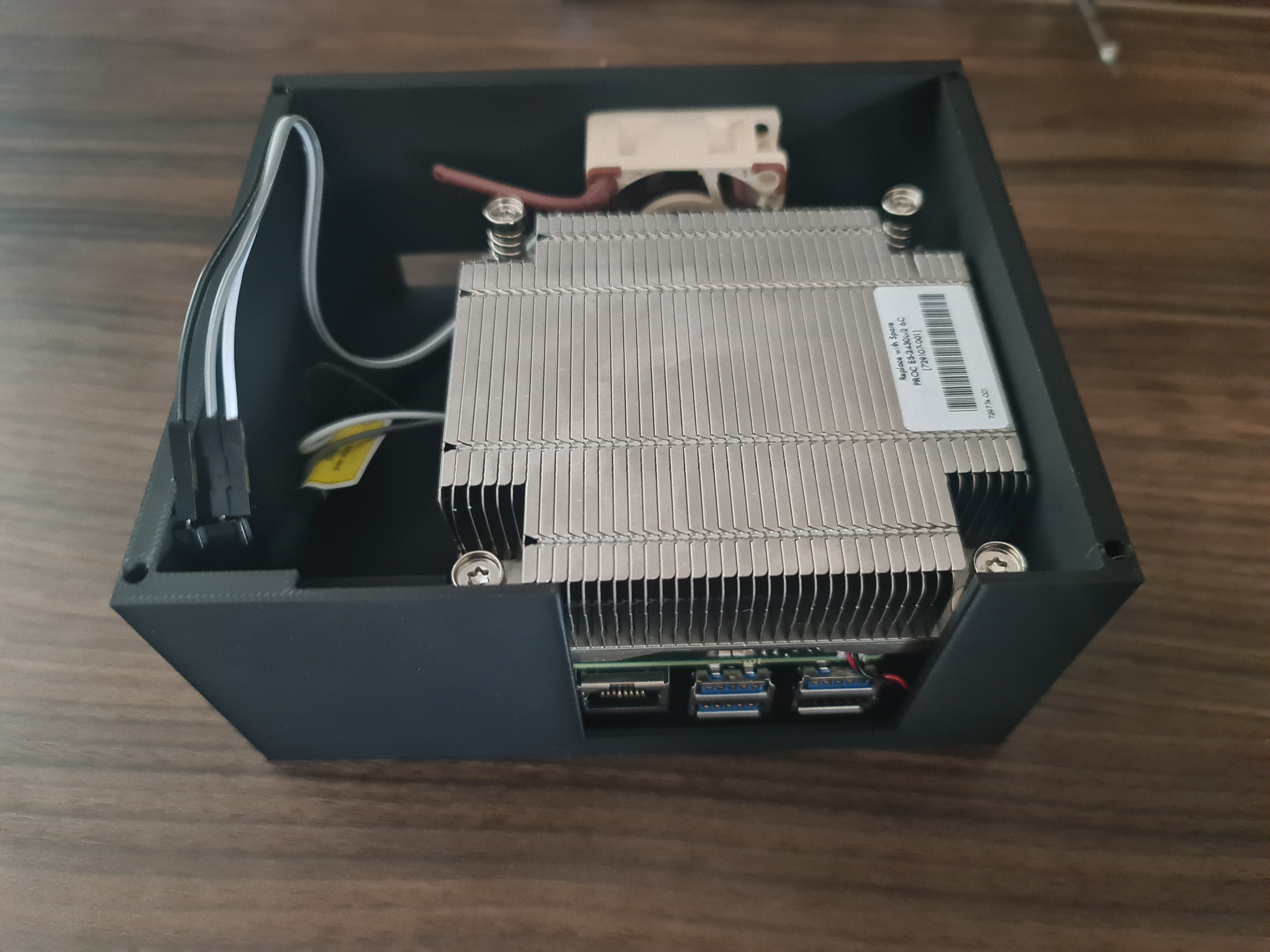
Now you can put the board into the case. Make sure you put the board in the right way, so the GPIO pins are on the left side. If you did not remove the antennas, make sure they are not in the way of the case.
You could also think about gluing the battery to the case, so it doesn’t move around. I didn’t do that, since I don’t plan on moving the case around a lot.
Closing it up
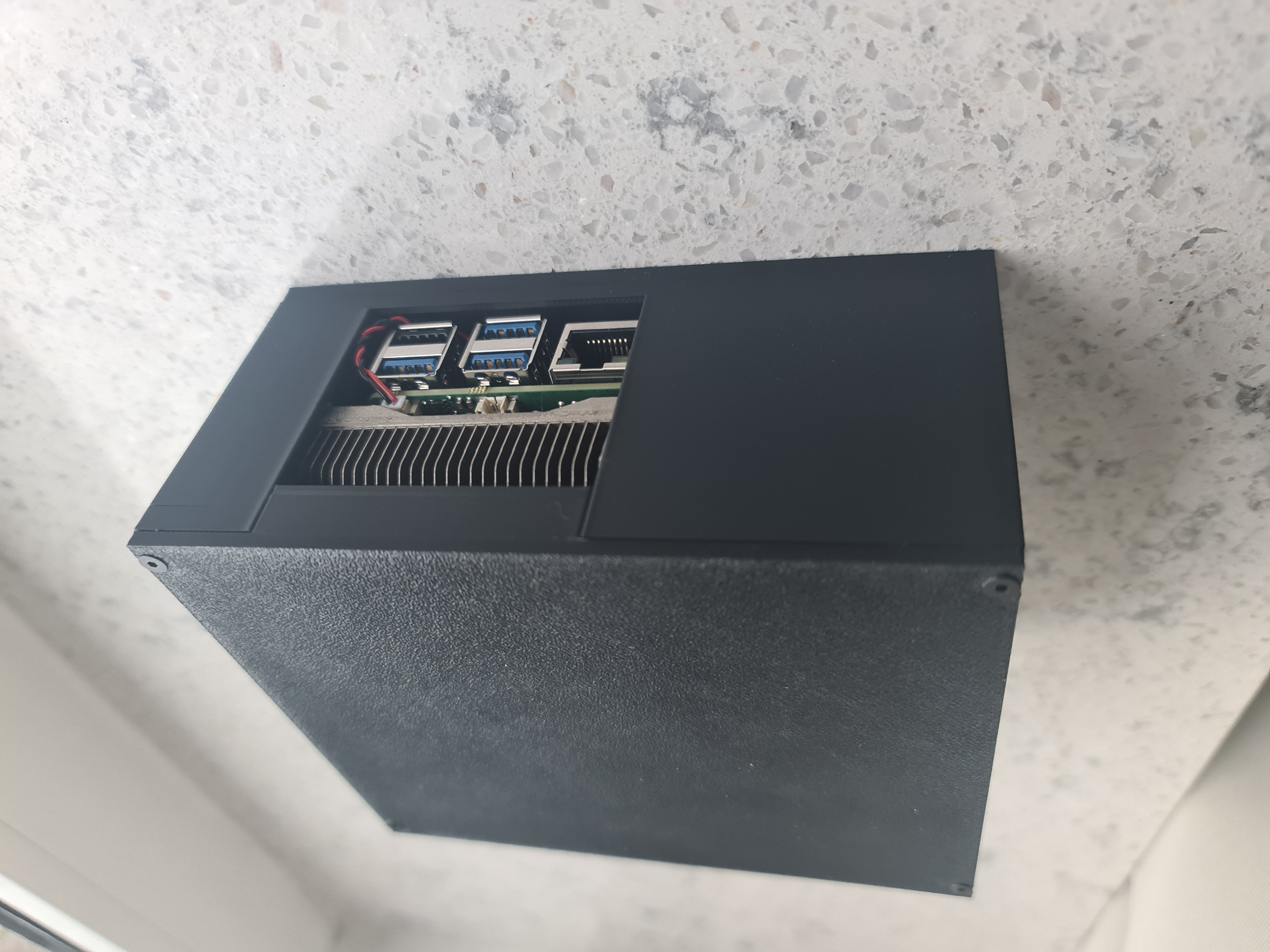
Now take the top part of the case and put it on top of the board. Make sure you align the holes with the brass inserts. The top also applies pressure to the top of the heatsink.
You are done! Now you can screw the screws into the brass inserts. Make sure you don’t screw them in too hard, since you might break the walls.
Next up: Part 6